Difference between revisions of "Blynk"
| Line 1: | Line 1: | ||
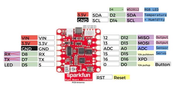
[[File:Sparkfun-Blynk-ESP8266-pins-map.jpg|600px]] | [[File:Sparkfun-Blynk-ESP8266-pins-map.jpg|600px]] | ||
| + | |||
| + | == Sparkfun-Blynk-ESP8266 Onboard-LED == | ||
| + | |||
| + | Auf dem Sparkfun-Blynk-ESP8266 Board befindet sich ein LED, der sich gut dazu eignet, um zum Beispiel den aktuellen Zustand eines Ausgangs darzustellen. Diese LED ist mit '''Pin 5''' verdrahtet und kann auch darüber in der App angesteuert werden. | ||
| + | |||
| + | |||
| + | '''Onboard-RGB-LED''' | ||
| + | * Board: [https://www.sparkfun.com/products/13794 Sparkfun-Blynk-ESP8266] | ||
| + | * Onboard-LED (eine ganz normale LED) | ||
| + | * Pin: 5 | ||
| + | * Example-Blynk-App-Settings (siehe unten) | ||
| + | * Example-Code (siehe unten) | ||
| + | |||
| + | |||
| + | <pre> | ||
| + | |||
| + | // Sparkfun-Blynk-ESP8266 Onboard-LED Example | ||
| + | |||
| + | ... | ||
| + | |||
| + | </pre> | ||
| + | |||
| + | <br> | ||
== Sparkfun-Blynk-ESP8266 Read Onboard-Button == | == Sparkfun-Blynk-ESP8266 Read Onboard-Button == | ||
Revision as of 16:44, 24 January 2021
Contents
Sparkfun-Blynk-ESP8266 Onboard-LED
Auf dem Sparkfun-Blynk-ESP8266 Board befindet sich ein LED, der sich gut dazu eignet, um zum Beispiel den aktuellen Zustand eines Ausgangs darzustellen. Diese LED ist mit Pin 5 verdrahtet und kann auch darüber in der App angesteuert werden.
Onboard-RGB-LED
- Board: Sparkfun-Blynk-ESP8266
- Onboard-LED (eine ganz normale LED)
- Pin: 5
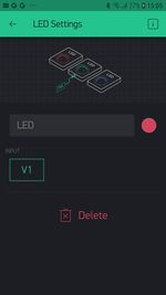
- Example-Blynk-App-Settings (siehe unten)
- Example-Code (siehe unten)
// Sparkfun-Blynk-ESP8266 Onboard-LED Example

...
Sparkfun-Blynk-ESP8266 Read Onboard-Button
Auf dem Sparkfun-Blynk-ESP8266 Board befindet sich ein Taster, der sich gut dazu eignet, um zum Beispiel den aktuellen Zustand einer Tür (Reed-Schalter) in der App sichtbar zu machen. Dieser Taster ist mit Pin 0 verdrahtet und kann ober einen virtuellen Pin gelesen werden.
Onboard-RGB-LED
- Board: Sparkfun-Blynk-ESP8266
- Onboard-Taster an Pin — kann auch über einen externen Taster zischen Pin 0 und GND geschaltet werden
- Example-Code (siehe unten)
- Example-Blynk-App-Settings (siehe unten)
// Sparkfun-Blynk-ESP8266 Read Onboard-Button Example

/* Comment this out to disable prints and save space */
#define BLYNK_PRINT Serial

#include <ESP8266WiFi.h>
#include <BlynkSimpleEsp8266.h>

// You should get Auth Token in the Blynk App.
// Go to the Project Settings (nut icon).
char auth[] = "YourAuthToken";

// Your WiFi credentials.
// Set password to "" for open networks.
char ssid[] = "YourNetworkName";
char pass[] = "YourPassword";

#define ButtonPin 0

int prevState = -1;
int currState = -1;
long lastChangeTime = 0;

void checkPin()
{
  // Invert state, since button is "Active LOW"
  // int state = !digitalRead(ButtonPin);
  boolean state = !digitalRead(ButtonPin);

  // Debounce mechanism
  long t = millis();
  if (state != prevState) {
    lastChangeTime = t;
  }
  if (t - lastChangeTime > 50) {
    if (state != currState) {
      currState = state;
      if (state == 0) {
        Blynk.virtualWrite(V1, 0);
        Serial.println("Button Off");
      }
      if (state == 1) {
        Blynk.virtualWrite(V1, 1023);
        Serial.println("Button On");
      }
    }
  }
  prevState = state;
}

void setup()
{
  // Debug console
  Serial.begin(9600);

  Blynk.begin(auth, ssid, pass);

  // Make ButtonPin default HIGH, and attach INT to our handler
  pinMode(ButtonPin, INPUT_PULLUP);
}

void loop()
{
  Blynk.run();
  checkPin();
}
Sparkfun-Blynk-ESP8266 Onboard-NeoPixel
Auf dem Sparkfun-Blynk-ESP8266 Board befindet sich eine RGB LED, die sich sehr gut dazu eignet, um zum Beispiel einen aktuellen Zustand anzuzeigen. Diese RGB LED vom Type WS2812 ist mit Pin 4 verdrahtet und kann über die Library Adafruit_NeoPixel.h angesteuert werden.
Onboard-RGB-LED
- Board: Sparkfun-Blynk-ESP8266
- LED-Type: WS2812
- Library: Adafruit_NeoPixel.h
- Pin: 4
- Example-Code (siehe unten)
- Example-Blynk-App-Settings (siehe unten)
// Sparkfun-Blynk-ESP8266 Onboard-NeoPixel Example

#define BLYNK_PRINT Serial
#include <ESP8266WiFi.h>
#include <BlynkSimpleEsp8266.h>
#include <Adafruit_NeoPixel.h>

// You should get Auth Token in the Blynk App.
// Go to the Project Settings (nut icon).
char auth[] = "YourAuthToken";

// Your WiFi credentials.
// Set password to "" for open networks.
char ssid[] = "YourNetworkName";
char pass[] = "YourPassword";

#define PIN 4
int stripR = 0;
int stripG = 0;
int stripB = 0;
int stripL = 0;

Adafruit_NeoPixel strip = Adafruit_NeoPixel(1, PIN, NEO_GRB + NEO_KHZ800);

BLYNK_WRITE(V1)
{
  stripR = param[0].asInt();
  stripG = param[1].asInt();
  stripB = param[2].asInt();
  showRGB();
}

BLYNK_WRITE(V2)
{
  stripL = 255 - param.asInt();
  showRGB();
}

void showRGB() {
  int r = stripR - stripL;
  if (r < 0) r = 0;
  int g = stripG - stripL;
  if (g < 0) g = 0;
  int b = stripB - stripL;
  if (b < 0) b = 0;

  strip.setPixelColor(0, strip.Color(r, g, b));
  strip.show();
}

void setup()
{
  // Debug console
  Serial.begin(9600);
  Blynk.begin(auth, ssid, pass);

  strip.begin();
  strip.show();
}

void loop()
{
  Blynk.run();
}
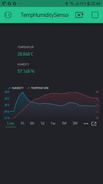
Sparkfun-Blynk-ESP8266 Onboard-Temp-Humidity
Auf dem Sparkfun-Blynk-ESP8266 Board befindet sich eine Temperatur- und Feuchtigkeitssensor, der sich sehr gut dazu eignet, um zum Beispiel das Raumklima zu erfassen. Diese I2C Sensor vom Type Si7021 ist mit Pin 2 und Pin 14 verdrahtet und kann über die Library SparkFun_Si7021_Breakout_Library.h ausgelesen werden.
Onboard Temperature and Humidity Sensor
- Board: Sparkfun-Blynk-ESP8266
- Sensor-Type: Si7021
- Library: SparkFun_Si7021_Breakout_Library.h
- Pin: 2 & 14 (werden von der Library automatisch gesetzt)
- Example-Code (siehe unten)
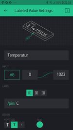
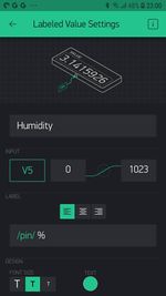
- Example-Blynk-App-Settings (siehe unten)
// Sparkfun-Blynk-ESP8266_Onboard-TempHumidity_Example

/* Comment this out to disable prints and save space */
#define BLYNK_PRINT Serial

#include <ESP8266WiFi.h>
#include <BlynkSimpleEsp8266.h>
// #include <DHT.h>
#include "SparkFun_Si7021_Breakout_Library.h"
#include <Wire.h>

// You should get Auth Token in the Blynk App.
// Go to the Project Settings (nut icon).
char auth[] = "YourAuthToken";

// Your WiFi credentials.
// Set password to "" for open networks.
char ssid[] = "YourNetworkName";
char pass[] = "YourPassword";

float humidity = 0;
float tempf = 0;
float tempc = 0;

//Create Instance of HTU21D or SI7021 temp and humidity sensor and MPL3115A2 barrometric sensor
Weather sensor;

BlynkTimer timer;

// This function sends Arduino's up time every second to Virtual Pin (5).
// In the app, Widget's reading frequency should be set to PUSH. This means
// that you define how often to send data to Blynk App.
void sendSensor()
{
  getWeather();
  printInfo();
  sendValues();
}

void setup()
{
  // Debug console
  Serial.begin(9600);

  Blynk.begin(auth, ssid, pass);
  // You can also specify server:
  //Blynk.begin(auth, ssid, pass, "blynk-cloud.com", 80);
  //Blynk.begin(auth, ssid, pass, IPAddress(192,168,1,100), 8080);

  //Initialize the I2C sensors and ping them
  sensor.begin();

  // Setup a function to be called every second
  timer.setInterval(1000L, sendSensor);
}

void loop()
{
  Blynk.run();
  timer.run();
}

//---------------------------------------------------------------
void getWeather()
{
  // Measure Relative Humidity from the HTU21D or Si7021
  humidity = sensor.getRH();

  // Measure Temperature from the HTU21D or Si7021
  // tempf = sensor.getTempF();
  tempc = sensor.getTemp();
  // Temperature is measured every time RH is requested.
  // It is faster, therefore, to read it from previous RH
  // measurement with getTemp() instead with readTemp()
}
//---------------------------------------------------------------
void printInfo()
{
  //This function prints the weather data out to the default Serial Port

  Serial.print("Temp:");
  Serial.print(tempc);
  Serial.print("°C, ");

  Serial.print("Humidity:");
  Serial.print(humidity);
  Serial.println("%");
}

void sendValues() {
  // You can send any value at any time.
  // Please don't send more that 10 values per second.
  Blynk.virtualWrite(V5, humidity);
  Blynk.virtualWrite(V6, tempc);
}
